A Simple Guide to E-Meter Verification & Commissioning
A Simple Guide to E-Meter Verification & Commissioning
Electrical contractors and operations technicians often struggle with the deceptively complicated process of verifying an electrical meter (e-meter). Whenever an electrical meter is ‘touched’ it is critical to verify the readings. APT has provided a simple guide with straightforward checks for anyone who wants to ensure that electrical meter values are accurate.
Please note that this process is NOT electrical meter calibration.
Meter calibration occurs in the factory when the meters are built and compares the new meter accuracy against an NIST (National Institute of Standards and Technology) standard. Verification is simply confirming that the meter is installed and reading values that match an independent check of current and voltage, as well as phase relationships between voltages and currents to get positive kilowatts from a meter measuring a load.
5 E-Meter Verification Pre-Requisites
To ensure the successful verification and commissioning of any electrical meter, you must focus on five (5) main elements:

1. Location
Electrical meter verification activities will include obtaining information regarding the location of the meter.
This location specific info consists of:
- Building
- Floor
- Column grid
- Electrical room or electrical equipment information
- Unique meter number
A Unique meter number is similar to ‘E1234.’
- The ‘E’ denotes an electric meter
- The four or five-digit number following is a unique identifier
- Alternatively, you can build a unique name with the source and load for the circuit
The location information and meter number is simply to ensure data collected is clearly tied to the location where the metering instrument is physically installed.
Below is an example of a Schneider PM8000 series meter with a ¼ DIN cutout in the electrical enclosure.

Electrical Meter flush mount typical PM8000
2. Voltage
In addition to identifying the location of the meter, you must determine the voltage of the circuit you are measuring. For instance, you need to know whether the meter voltage connects through a wye or delta configuration.
A 3-phase power system uses two types of circuits to maintain constant loads across the three hot wires:
Delta configurations connect the three phases like a triangle. There are four wires in a delta system (three hot wires and one ground wire) with no neutral conductor.
Wye connections, on the other hand, use a star configuration. In a wye system, there are five wires – three hot wires, a single neutral and one ground wire.

On a typical 120/208V system, both the Delta and Wye systems measure 208VAC between any two hot wires. However, a 3-phase Wye system also measures 120VAC between any hot wire and a neutral wire. In other words, the Wye system’s neutral wire allows two different voltages and powers both 3-phase and single-phase devices.
Make sure to document the PT ratio and the reference voltage, especially concerning potential transformers (PT). A suitably rated fuse should protect all voltage metering circuits for the arc flash rating of the electrical equipment where the meter is installed.
Nominal Voltage is the typical RMS line to line voltage value of the electrical equipment (i.e. 480V, 208V) at the meter installation site. Furthermore, the nominal voltage sets the power quality threshold for voltage deviation alarms.
installations that exceed 600 volts line to line require the use of a Potential Transformer to reduce the voltage to a lower value. So, be sure to size and wire the PT to convert the primary voltage to usable secondary voltage. Further, configure the PT ratio into the meter (this is essential) to get accurate energy calculations.
Below is an example of a Schneider Electric PM8000 series meter with APT

Reference Voltage is the neutral or ground voltage reference to measure in relation to all metered values. Typically this is a neutral or ground reference terminal block within the electrical equipment where the meter is wired. After that, you must remember to label and terminate Voltage Reference (VREF). Note that the Voltage Reference VREF must include protection suitable for the fuse size, per the meter installation specifications.
Below is an example of a Schneider Electric PM8000 series meter directly connected

3. Current
Next, confirm that the maximum current value for the meter circuit is limited by a circuit breaker, fuse or other overcurrent protection device. Firstly, physically verify the meter’s Current Transformer (CT) size markings, and document the CT ratio.
Note that markings at Current Transformer terminals usually indicate the CT polarity
Therefore, It is good practice to test each time to ensure that CT polarities are always correct. So, when servicing or removing meters, protect all current metering circuits with a shorting block to safely shunt the current transformer(s).
Another unique aspect of Current Transformers is the size and orientation of the transformer ‘donut’ opening relative to the phase conductors. So, ensure that the physical opening of the ‘donut’ is sufficient to encompass all of the current-carrying conductors per phase. In other words, don’t apply a CT to one conductor in a parallel run. You cannot assume that all parallel conductors carry the same current.
Similarly, placing a CT around ALL three phases will not provide an accurate reading of the current flow. The orientation (customarily indicated on the CT with an arrow or a dot) must be consistent across all installations.
Below is an example of a Split-Core Current Transformer

Below is an example of a Schneider Electric PM8000 series meter

Wiring for CT inputs at the meter:
- (I1+, I1-) phase A
- (I2+, I2-) phase B
- (I3+, I3-) phase C
- (I4+, I4-) Phase Neutral
Additionally, some customers choose to install Neutral or Ground current monitoring CTs.
4. Control Power
Your meter may derive it’s control power independently from a DC battery system or Uninterruptible Power Supply (UPS). Additionally, it may come from the control power transformer in the electrical equipment. However, many meters can directly connect to the voltage connections for control power.
Regardless of the situation, ensure you understand the control power for this meter. Meanwhile, make sure all control power circuits require protection by a fuse suitable for the electrical equipment surrounding the meter.
Again, let’s use a Schneider Electric PM8000 series meter as an example. Verify instrument control power L1 and L2 connections are set up correctly with appropriate fuse size protection per meter installation instructions.

5. Communications
Modern electrical meter installations typically communicate information to a remote monitoring control system on a computer or network server. Moreover, depending on the type of meter connection (ports) you have, you can transmit data using serial cables, Ethernet cables, or a nearby cellular tower.
There are multiple communication ports on every meter, including serial, Ethernet, and cellular. Therefore, documentation is necessary to understand each communication port’s physical connections, configurations, and testing. In many instances, a single meter communicates on several ports simultaneously.
Communications are the leading reason for APT’s service business calls, whether at a startup or during a customer’s network change.
E-Meter Ethernet Port Settings
Nowadays, modern electrical meters transmit data via Ethernet connections to the power monitoring server. Here is another example of a Schneider Electric PM8000 meter and its ION Setup configuration software demonstrating typical Ethernet Port settings set on the Ethernet COM port.

Note that serial meters are typically connected in a “daisy chain” communication loop to leverage the low cost of serial cables and connect many meters and devices to a single Ethernet gateway. Adding a serial meter to a serial loop requires attention to detail; it is one of the most common errors made in replacing or installing a meter.
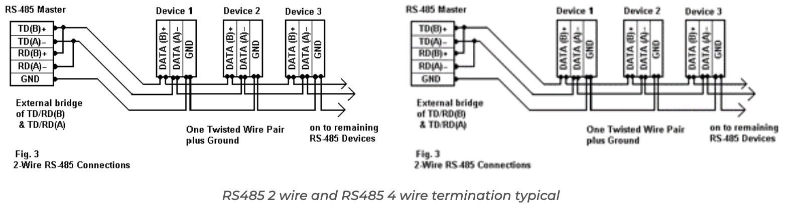
Serial End Of Line (EOL) resistor
Serial termination or End Of Line (EOL) resistors that match the cable’s characteristic impedance are crucial for minimizing reflections, communication error rates, and electromagnetic emissions.
It is essential to use termination resistors with long cable lengths to ensure data integrity and reduce errors. However, adding termination resistors can sometimes result in a voltage drop. As a result, this drop causes the devices furthest from the gateway to lose communication when adding termination resistors on very long cables. In such cases, removing termination resistors or splitting the loop into shorter segments may be the key to restoring communication.
You can test communications via a meter serial port by watching for flashing LEDs on the serial port. Next, connect directly to the meter with a serial cable and launch the ION Setup on your laptop.
Below is an example of a USB to a serial port connector that can facilitate a direct serial connection with your laptop in the field.

E-Meter Cellular Modem Settings
Cellular modems are one of the best solutions when you cannot install Ethernet or serial cables easily.
Below is an of a cellular modem for a customer’s private network.

How to Document Meter
Configuration & Program Meters
Next, you’d want to document the meter settings on a form or report for record-keeping. Below is an example.

1. Scan the meter calibration certificate
The factory ships all meters with a meter calibration certificate in the box tracing the meter’s calibration back to NIST standards. If the meter calibration certificate is inside the box or enclosure during a new meter installation, scan the certificate and attach it to the meter documentation form.

2. Verifying meter values with ION Setup
Using the Schneider Electric ION Setup meter configuration tool via a laptop computer connected directly to the meter. As a result, you will be able to see the meter in real-time and verify the voltage displayed accurately.
What to Verify:
- Verify the voltage display matches the expected value.
- Confirm voltage at VREF terminals with a digital multimeter.
- Verify that the kW you are measuring is a positive.
- A positive measurement confirms that the CT wiring and orientation are correct.
- Verify the current display is accurate to the load you are measuring.
- Ideally, the load you are measuring should be at least 10% of the CT rating.
Again, the load you are measuring should be at least 10% of the CT rating to provide an accurate reading. Applying a known load through the measured load is the best way to determine if the measurement seen at the meter correctly configured.

Review the phasor diagram to determine that the VREF and current transformers (CT) are aligned and in phase. In industrial or commercial induction loads, the voltage leads the current and produces a lagging power factor with positive kilowatts. A leading power factor or negative kilowatts are signs that a CT is inverted or the phase relationships between voltages and currents are incorrectly wired.

Troubleshooting
Types of wiring problems
Before you suspect wiring, check to ensure the meter is programmed correctly with the correct PT and CT ratios and the VOLTS MODE setting is right. Therefore, depending on the configuration, there can be 3 CT and 3 PT secondary windings (12 conductor ends). As a result, ensure you apply these to the meter with the correct polarity. These could be misconnected without proper commissioning testing, causing the meter to display incorrect readings.
Wiring errors can consist of any combination of the following:
- Swapped current phases
- Incorrect current polarities
- Swapped voltage phases
- Incorrect voltage polarities
Most of the above wiring errors will produce correct voltage and current values but incorrect W, VA, VAr, and Power Factor values. Note that a negative kW value indicates the wrong polarity on the load.
When the meter has zero values for current and load is present
- Confirm test switches are closed
- Verify the shorting pins were removed at any CT shorting blocks (This process allows current flow through the meter)
If the meter displays zero values for voltage
- Confirm all fuses are present, good and the fuse holder is closed
When the voltage displays an unexpected value
- Check PT ratio settings
- Check volts mode setting
TIP
If the meter current displays in KiloAmps instead of Amps, change the meter CT primary and CT secondary ratio to use 1A and the secondary CT ratio. For instance, if the Primary Current Transformer is 2000A and the Secondary Current Transformer is 5A, the meter will display the Amperage readings in KiloAmps.
Instead, use the same ratio 2000:5 = 400:1 and program the primary CT as 400A and the secondary CT as 1A. Essentially, this is the same mathematical relationship as 2000 A/ 5 A. However, the meter displays the current in amps.
Common CT Ratios Translated from 5A secondary to 1A secondary
E-Meter Verification
Lastly, you can verify voltage and current by comparing the meter values to an independent digital multimeter. Here is what the meter verification process entails.
E-Meter verification
To verify the electrical meter, apply a known or existing load through the current transformers with control power and measure the resulting current and voltage with an independent instrument.
Voltage verification (V1, V2, V3)
You can verify meter values with a digital multimeter by checking the voltage inputs to the VREF inputs. If a PT is used, the voltage measured with a digital multimeter will need to be multiplied by the multiplier to obtain the actual voltage measured.
The field verification must match the meter reading by plus or minus 5% to pass. A failing reading differs more than 5% between the Digital MultiMeter (DMM) and the meter display.
Voltage Verification Table

Current verification (Ia, Ib, Ic)
To check the current inputs to the meter, use a digital multimeter with a current probe. Whenever possible, measure the actual load current on the conductors carrying the current during each phase rather than attempting to measure the secondary current (which is much lower in magnitude). Likewise, field verifications must match meter readings to within 5% to pass. A failing reading differs by more than 5% from the reading on the Digital MultiMeter (DMM).
Current Verification Table

New meters usually require a load placed on the meter to verify the current reading. So, ideally, you would coordinate with the contractor or building staff to get sufficient loads to take measurements at the meter location. Existing meters typically have a current load against which you can use to compare.
APT E-Meter Verification & Commissioning
APT can help you verify and commission your meters, or even help you build a specification to ensure this critical process gets done right the first time for new construction or projects.
Above all, we provide full service support for customers and contractors who demand accurate data from their metering systems, relays, generators, automatic transfer switches, Uninterruptible Power Supplies (UPS). As a result,, many clients trust APT to independently verify their on site distributed generation, solar PhotoVoltaic (PV) arrays, battery storage, fuel cells, or microgrids and compare to the electric utility.
Andrew E. Taylor, P.E. | APT Chief Executive Officer